


Working of Project

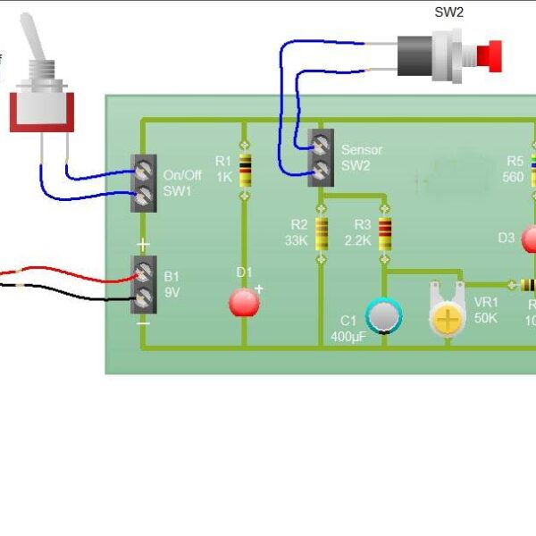
The block diagram of the Frequency counter using Arduino is shown in the above figure. The circuit is simple, an LCD is interfaced with Arduino to display the measured frequency of the signal. The frequency generator circuit using 555 to generate the pules. The aim of the project is to design a simple digital frequency counter circuit using Arduino UNO and 555 Timer IC. The working of the project is very simple and is explained here. As mentioned earlier, the 555 Timer IC is configured to operate in Astable mode. Hence, the output of the 555 Timer IC (or rather the signal generator circuit) is a pulse with variable frequency (varied using potentiometer). This pulse is given as input signal to the Arduino UNO at one of its digital I/O pins. In the Arduino, we make use of a function called ?pulse In ();? The function pulse In can be used to read either LOW or HIGH pulse on a digital I/O pin and returns the length of the pulse in microseconds. For example, if the pulse In function is used to read a HIGH pulse on a pin, it waits for the pin to go HIGH. Once the pin goes HIGH, it starts the timer and runs until the pin goes LOW. The duration (in microseconds) of this HIGH pulse is then returned. In our project, we are calculating the duration of the HIGH pulse and LOW pulse and by adding them together, we get the period of the input signal. The inverse of this value gives the frequency of the signal which is displayed on the LCD. Frequency Meter can measure frequencies up to 20 KH.


debamon –
really good product.