


Solar Home Lightning Remote Controlling System Using ESP8266
100% OUTPUT GUARANTEE
GET PROJECT DOCUMENTS
1.Synopsis
2.Report
3.PPT
4.Soft CD Copy
5.Mobile APP
Customer Support
24X7 Customer Support through WhatsApp or mail
WhatsApp:- +91 080-2574316
Mail ID:- info@sharvielectronics.com
sales@sharvielectronics.com
INTRODUCTION
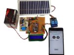
The IoT based Solar Home lighting remote controlling system is designed to operate with solar energy. The solar panels connected will distribute power to the system and the system will be able to control the switch on and off of two bulbs connected. Also it will show the status of the bulbs on a 16X2 LCD connected. The project consist of a Solar Panel to provide power to the circuit, a Wi-Fi microchip to control the bulbs as per the input received through mobile application and display the data on mobile application and the LCD. The Internet of things (IoT) is a system of interrelated computing devices, mechanical and digital machines provided with unique identifiers (UIDs) and the ability to transfer data over a network without requiring human-to-human or human-to-computer interaction. The definition of the Internet of things has evolved due to the convergence of multiple technologies, real-time analytics, machine learning, commodity sensors, and embedded systems.
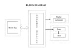
The block diagram of solar home lighting remote controlling system consist of following blocks:
- NodeMCU ESP8266
- Mobile Application
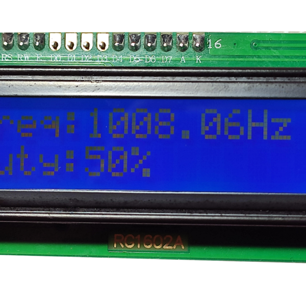
- 16X2 LCD
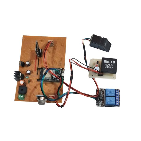
- Relays and bulbs


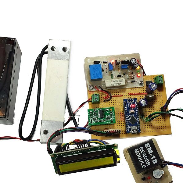
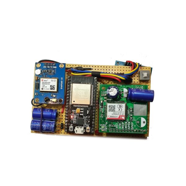
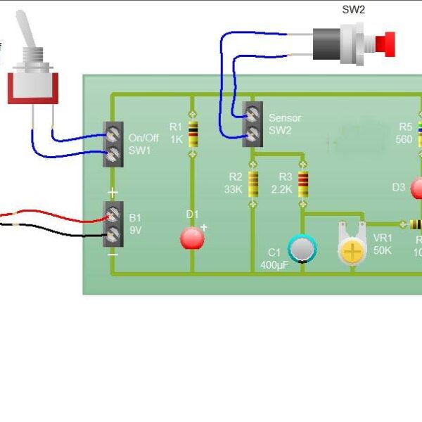
Circuit Working
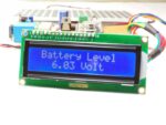
The main element of the circuit is Wi-Fi microchip ESP8266. It takes data from the mobile application and sends it to the relay control circuit. The ESP8266 gets power from the solar panel. It generates hotspot of its own. The mobile having the lighting remote control application will get the Wi-Fi through this hotspot. When the switch on or switch off command will be pressed in this mobile application, it will send signal to the ESP8266. ESP8266 will send command to the relay through transistor. The relay will switch ON and OFF according to that. As per the switch ON and OFF of the relay, the bulb connected will be switched ON or OFF. Also the LCD and mobile application will get the command from the microchip and will display the bulb status and 6V battery status.
PROJECT TARGET
To install the system in any place that requires switching on and off the bulbs through mobile
Application
- Home
- School
- Collages
- Offices
- Factories
- Hospitals etc.
Note: We are Providing Printed Circuit Board and general-purpose PCB Based on Customer Requirements.


Reviews
There are no reviews yet.