


PHASE ANGLE CONTROLLER SYSTEM
100% OUTPUT GUARANTEE
GET PROJECT DOCUMENTS
1.Synopsis
2.Report
3.PPT
4.Soft CD Copy
Customer Support
24X7 Customer Support through WhatsApp or mail
WhatsApp:- 080-25743168
Mail ID:- info@sharvielectronics.com
sales@sharvielectronics.com
INTRODUCTION
There are two different types of TRIAC control used to control the AC power flow:
ON-OFF Control,Phase control
These are the two AC output voltage control techniques. In On-Off control technique TRIACs are used as switches to connect the load circuit to the ac supply (source) for a few cycles of the input ac supply and then to disconnect it for few input cycles. The TRIACs thus act as a high speed contactor (or high speed ac switch). In phase control the TRIACs are used as switches to connect the load circuit to the input ac supply, for a part of every input cycle. That is the ac supply voltage is chopped using, thyristors during a part of each input cycle. The TRIACs switch is turned on for a part of every half cycle, so that input supply voltage appears across the load and then turned off during the remaining part of input half cycle to disconnect the AC supply from the load. There are 10 phases of angle control. For each one, the angle is shifted to 18 degree. So when the increment and decrement push buttons are pressed for 10 times, a total of 180 degree is shifted at the AC input.
![]()

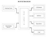
The block diagram of Phase Angle Controller consists of the following elements:
1. Switching Circuit
2. Zero Crossing Detector
3. Microcontroller PIC16F877A
4. LCD
5. Indicators
6. Optoisolator
7. Load
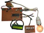
Circuit Working
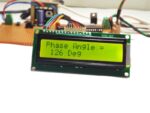
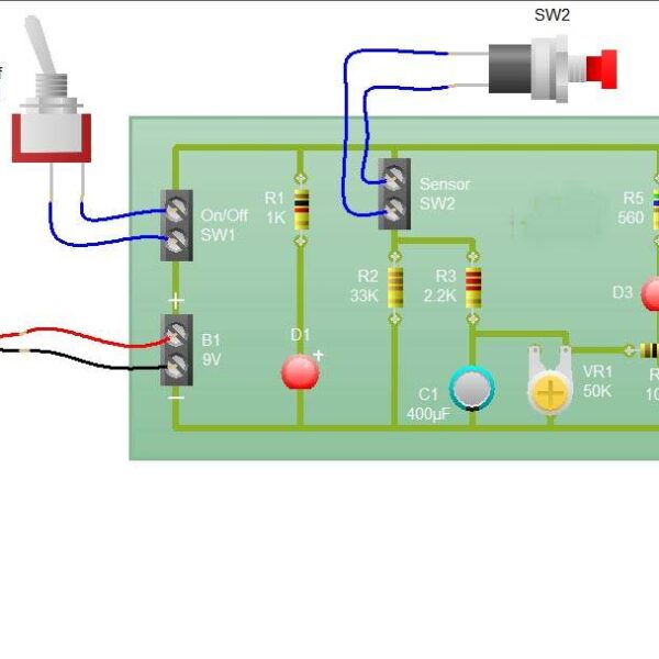
The main purpose of this project is to control the phase angle of the AC voltage coming into the circuit. The main purpose of controlling the phase angle is handled by microcontroller PIC16F877A. There are three push-button switches connected to the microcontroller and a bulb connected to the AC supply. This same AC is also tapped through a zero-crossing circuit to the microcontroller. 230V/50Hz AC supply is stepped down to 9V AC rms through a 0-9V step down transformer. This 9V AC rms is given to a 4N35 optocoupler. This optocoupler will give a spiked voltage when the AC rms reaches its peak. This spike current is boosted through a NPN transistor and given to the microcontroller as input, this functionality is zero-crossing detector. Through this, the microcontroller understands that the AC voltage is at peak voltage of its cycle and in turns through program it cuts the voltage and tries to control the phase angle. One push button connected is for increment and another for decrement of phase angle. Third push button switch is for on/off of bulb through TRIAC switch. There are 10 angles of phase shift designed. Each is of 18 degrees. So when the increment or decrement push button is pressed one time, it shifts the phase angle of the AC voltage to 18 degree. If it is pressed 10 times, a total of 180 degree phase shift is earned. When the increment or decrement push button is pressed, the microcontroller sends the input to the optocoupler MOC3021. This optocoupler is connected to a TRIAC which is acting as a switch for load bulb connected. This switches on the bulb at the phase angle calculated by the microcontroller. When any decrement or increment push button is pressed, the corresponding LED glows. Also at the same time the microcontroller sends input to the LCD as well to display the phase angle data. There is a push button switch connected at the MCLR pin of the microcontroller. Whenever this push button is pressed, the microcontroller resets and everything comes to initial setting.
PROJECT TARGET
Target of this project is to make a controller circuit which controls the phase of the ac waveform by ‘α’ degrees with the delay time of ‘t’ seconds.
Application
1.Factory
2.Home
3.Industry
Note: We are Providing a Printed Circuit Board and general-purpose PCB Based on Customer Requirements.


Reviews
There are no reviews yet.